RJ45 Color Code and Diagram: A Complete Guide for Network Cabling
NETWORKING · CABLING REFERENCE
RJ45 Color Code and Diagram: The Complete 2026 Wiring Guide
Every pin, every color, both standards — plus a crimping walkthrough that actually holds up under a cable tester.
When it comes to Ethernet networking, understanding the RJ45 color code and diagram is essential. Whether you’re setting up a small home network or managing a data center’s structured cabling, wiring the eight conductors in the right order is what separates a stable gigabit link from a flaky one that drops under load.
This guide covers what an RJ45 connector actually is, the difference between the T568A and T568B wiring standards, how the pinout maps to straight-through and crossover cables, and a step-by-step crimping process you can follow with a basic toolkit. It also covers newer details the original guide skipped — Cat7/Cat8 wiring, how PoE interacts with the color code, and where to double-check the standard if you want the primary source.
What is an RJ45 Connector?
An RJ45 (Registered Jack 45) is an 8-pin, 8-position modular connector used almost universally for Ethernet networking. You’ll find it crimped onto the ends of Cat5e, Cat6, and Cat6a cables, plugging into the Ethernet ports on computers, switches, routers, and patch panels.
RJ45 connectors terminate twisted-pair cabling used in structured network wiring, and the connector itself is dumb — it’s the order the eight wires go into it that determines whether the link works, matches your patch panel, and resists interference.
Why the RJ45 Color Code Matters
The color code inside an RJ45 connector gives every technician the same reference point for matching and ordering the four twisted pairs. Following a standard wiring scheme keeps paired wires paired — which is what actually cancels crosstalk — and keeps every cable you build compatible with the next person’s patch panel.
Get the order wrong and you risk:
- Intermittent or failed network links
- Degraded signal quality and higher error rates
- Cables that don’t match your patch panel or wall jacks
- Hours of troubleshooting for a problem that’s really just pin 3 and pin 6 swapped
RJ45 Pin Numbering Diagram
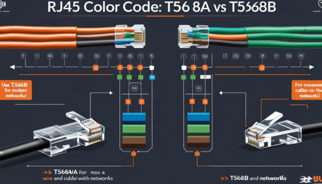
Pins are numbered 1–8 left to right with the clip facing away from you and the cable pointing down. The diagram below shows that numbering against both standards side by side.
T568A vs. T568B Wiring Standards
There are two wiring standards recognized under the TIA/EIA-568 specification for RJ45 termination. Both use the same eight colors — only pins 1-2 and 3-6 swap places.
T568A Standard
Used mainly in residential installations and required by default on U.S. federal government contracts.
| Pin | Color |
|---|---|
| 1 | White/Green |
| 2 | Green |
| 3 | White/Orange |
| 4 | Blue |
| 5 | White/Blue |
| 6 | Orange |
| 7 | White/Brown |
| 8 | Brown |
T568B Standard
The more common standard for commercial networks and data centers, and the default most pre-made patch cables ship with.
| Pin | Color |
|---|---|
| 1 | White/Orange |
| 2 | Orange |
| 3 | White/Green |
| 4 | Blue |
| 5 | White/Blue |
| 6 | Green |
| 7 | White/Brown |
| 8 | Brown |
Straight-Through vs. Crossover Cables
Straight-Through Cable (Same Standard on Both Ends)
Used to connect different device types — computer to switch, or router to modem. Wire both ends T568B (or both T568A) and you have a standard patch cable.
Crossover Cable (T568A on One End, T568B on the Other)
Used to connect similar devices directly — switch to switch, or computer to computer — without a switch in between. If you’ve also read our guide on how to make a crossover cable, this is the same A/B pairing applied end to end.
How to Crimp an RJ45 Connector — Step by Step
Tools needed: RJ45 crimping tool, Ethernet cable (Cat5e/Cat6), RJ45 connectors, wire stripper, and a cable tester (strongly recommended, not optional).
- Strip the cable jacket. Remove about 1 inch (2.5 cm) of outer insulation to expose the four twisted pairs.
- Untwist the wires. Carefully untwist each pair only as far as needed and straighten all eight conductors.
- Arrange by color code. Pick T568A or T568B and line the wires up in that exact pin order.
- Trim evenly. Cut the wires flush so they’re all the same length before inserting.
- Insert into the connector. Push until every wire is visible at the tip, seated in its own channel.
- Crimp. Seat the connector in the crimping tool and press firmly until it locks the contacts through the insulation.
- Test. Run a cable tester on both ends to confirm continuity and correct pin mapping before relying on the cable.
Common Mistakes to Avoid
- Mixing T568A and T568B unintentionally, outside of a deliberate crossover build
- Not pushing wires fully into the connector before crimping
- Leaving too much untwisted or exposed copper, which invites interference
- Skipping the cable tester and assuming a clean crimp means a working link
RJ45 Color Code Across Cable Categories
Cat5e, Cat6, Cat6a
All three use the same T568A/T568B pinout. Cat6 adds a plastic spline to separate pairs and reduce crosstalk; Cat6a thickens the shielding and jacket for full 10-gigabit performance over longer runs.
Cat7 and Cat8
Cat7 and Cat8 also follow the standard color code on their RJ45-terminated ends, though Cat7 is more often terminated in GG45 or TERA connectors in fully shielded installations. Where Cat7/Cat8 cable is terminated in RJ45, the same eight colors and pin order apply.
Shielded vs. Unshielded (STP vs. UTP)
STP is used in high-interference environments like industrial floors and near heavy machinery; UTP is sufficient for most home and office runs. The color code itself doesn’t change between the two.
RJ45 Wiring and Power over Ethernet (PoE)
PoE delivers power over the same RJ45 cable that carries data, using either the two data pairs (pins 1-2 and 3-6, the “Alternative A” mode) or the two spare pairs (pins 4-5 and 7-8, “Alternative B”), depending on the switch or injector. The color code and pin order stay identical to a standard T568A/T568B termination — PoE doesn’t require any special wiring, just cable and connectors rated for the current draw of the powered device.
Summary: Full RJ45 Color Code Table
| Pin | T568A Color | T568B Color |
|---|---|---|
| 1 | White/Green | White/Orange |
| 2 | Green | Orange |
| 3 | White/Orange | White/Green |
| 4 | Blue | Blue |
| 5 | White/Blue | White/Blue |
| 6 | Orange | Green |
| 7 | White/Brown | White/Brown |
| 8 | Brown | Brown |
Whichever standard you pick, consistency across every jack, patch panel, and cable in a network matters more than which one you chose.
Frequently Asked Questions
Can I mix T568A and T568B in a network?
It isn’t recommended unless you’re intentionally building a crossover cable. Stick to one standard for every connection to avoid confusing future troubleshooting.
Is there a performance difference between T568A and T568B?
No. Both wiring schemes carry data identically. The choice comes down to matching existing infrastructure and staying consistent, not speed.
What happens if the RJ45 is wired incorrectly?
Incorrect wiring can cause dropped connections, reduced link speed, a device that never links up at all, or interference from crossed pairs.
Are crossover cables still needed?
Most modern devices support Auto MDI-X, which automatically senses and adjusts for a straight-through cable, but it’s still a core skill worth knowing.
Do I need special RJ45 connectors for Cat6 cables?
Yes — Cat6-rated connectors are built to accommodate thicker conductors and, in shielded builds, the metal shielding, so use connectors matched to your cable category.
Does the color code change for PoE cabling?
No. PoE uses the same T568A/T568B pin order; what matters for PoE is that the cable and connectors are rated for the current the powered device draws.
Final Thoughts
The RJ45 color code looks like a small detail, but it’s the difference between a network that just works and one you’ll be troubleshooting for an afternoon. Pick T568A or T568B based on what your existing infrastructure uses, stay consistent across every cable you terminate, and always finish with a cable tester rather than trusting the crimp by eye.
For related wiring projects, see our step-by-step guide to making a crossover cable.